
How to Plan and Build a Straight, Secure Vinyl Fence
Calculate post centers from the actual installed panel width, routed engagement or bracket geometry, post configuration, and gate openings.
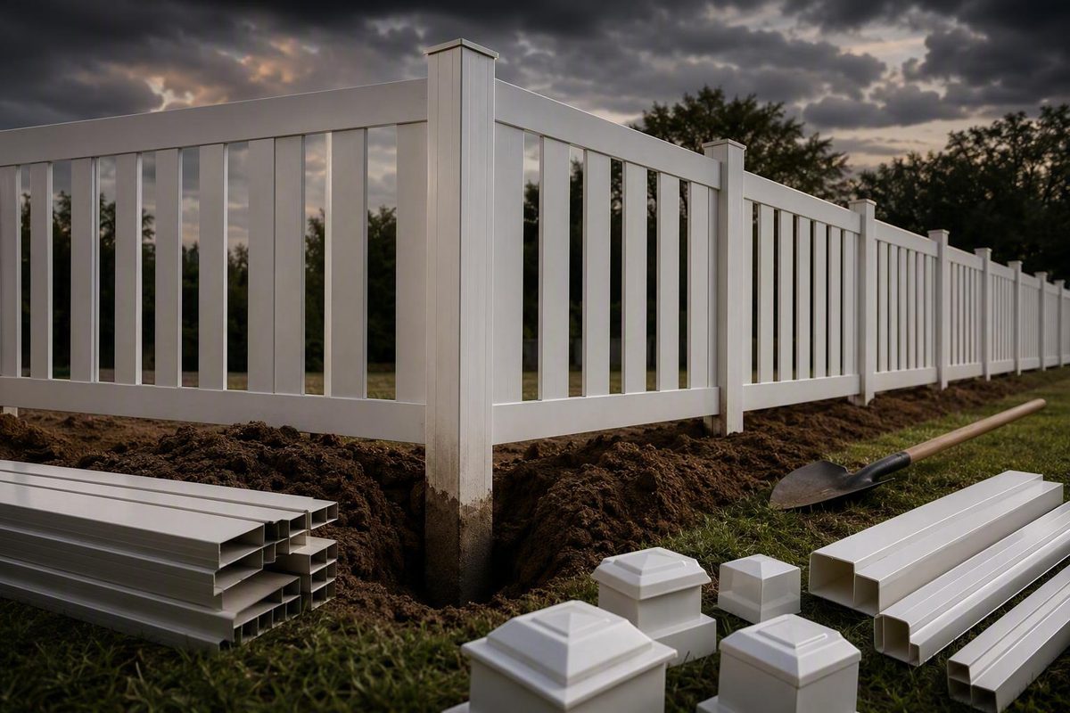
Installing vinyl fence successfully is not a matter of memorizing one post depth or panel spacing. It is a system-first project: identify the exact components, clear the legal and physical route, calculate openings from actual product dimensions, reconcile the footing design with local requirements, and keep every post correctly positioned until its footing is ready to carry a load.
That distinction matters because vinyl fences do not all connect or cross slopes in the same way. A routed privacy system, bracket-mounted picket fence, rackable panel, driven-post system, and reinforced gate can require substantially different methods. This guide provides a chronological planning workflow, but the instructions for the purchased fence and gate must supply the model-specific dimensions, hardware, clearances, and assembly details.
Start by Identifying the Fence System and the Limits of Generic Advice
There is no single installation method for every vinyl fence. Before measuring the site or ordering a complete package, identify the system you intend to install.
Common configurations include:
- Routed-post systems: Rails or panel ends engage openings formed in the posts. Line, corner, end, gate, and blank posts may have different routing.
- Bracket-mounted systems: Panels or rails attach to brackets positioned and fastened according to the product instructions.
- Driven-post or no-dig systems: Metal supports are driven into the ground, with vinyl posts or sleeves fitted over them.
- Rackable systems: Compatible panels change shape within a documented range to follow a grade.
- Stepped systems: Individual bays remain level but rise or fall at successive posts.
- Proprietary systems: Rails, locking tabs, stiffeners, connectors, fasteners, or inserts work only with a particular product family.
These categories can overlap. Do not assume that two vinyl products—even products sold by the same company—assemble alike. Buy Direct Vinyl Fence, for example, publishes separate resources for privacy, picket, semi-privacy, ranch-rail, specialty, and gate products, illustrating why the exact product instructions matter (review its product-specific installation resources).
Before planning the layout, inventory the selected system:
- Fence style and model
- Nominal and actual panel dimensions
- Actual installed panel width
- Line, corner, end, blank, and gate posts
- Rails, routed connections, brackets, or locking components
- Model-compatible fasteners
- Post caps
- Gate kit and hardware
- Required inserts, stiffeners, or reinforcement
- Approved footing or anchoring method
- Components for corners, slopes, shortened bays, and transitions
Treat gates as separate products rather than fence panels with hinges added later. Privacy, picket, semi-privacy, and ranch-rail products can also have different post types and assembly sequences.
The exact instructions for the purchased model should establish:
- Post-center spacing
- Rail or panel engagement
- Temperature-movement clearances
- Bracket locations and fasteners
- Compatible footing or anchoring methods
- Post orientation
- Assembly order
- Permitted cutting or shortening
- Approved slope treatment
- Gate reinforcement and hardware
Applicable local law, permit conditions, inspections, and authority-approved structural requirements must also be satisfied. Product instructions govern compatibility with the fence system but cannot waive a legal requirement. If the two appear to conflict, stop and seek clarification from the manufacturer and the relevant local authority.
Universal guidance is limited to practices such as verifying conditions, using actual measurements, maintaining alignment, checking posts repeatedly, and stopping when the site falls outside the documented instructions. Figures such as burying one-third of a post, digging a nominal 10-inch hole, spacing posts 6 to 8 feet apart, or using a fixed gravel depth appear in general consumer guidance, but they are not specifications for every fence or site (compare Lowe’s general figures with its local-condition caveat).
This is also more involved than snapping panels together. The work can include measurement, excavation, lifting, post setting, alignment, footing materials, and assembly of long components. Home Depot classifies vinyl-fence installation as advanced, describes it as a multi-day project, and recommends at least two people (see its project overview). A short, level run without gates may be realistic for an experienced DIYer; a long privacy fence with difficult soil, slopes, and multiple gates is a different project.
Complete the Boundary, Rules, and Utility Checks Before Digging
The first physical task is not staking the line. It is determining whether the intended route can legally and safely be used.
Complete this pre-dig checklist:
- Confirm the property boundary.
- Identify recorded or apparent easements.
- Ask the applicable local authority about setbacks.
- Check fence-height and design restrictions.
- Determine whether a permit is required.
- Identify required inspections.
- Review HOA or neighborhood rules.
- Check historic-district restrictions where applicable.
- Complete the applicable underground-utility location process.
- Verify gate locations against access and local requirements.
- Walk the route for physical constraints.
Requirements vary by jurisdiction, so obtain permit, setback, inspection, and design information from the authority that governs the property rather than treating a general installation guide as legal advice. Commercial pre-installation guidance likewise identifies boundaries, permits, local rules, and HOA restrictions as issues to resolve before purchasing or digging (see Weatherables’ planning checklist).
Existing fences can sit inside a property line or reflect an earlier owner’s assumption. When the boundary cannot be established confidently, use a qualified surveyor before committing materials or excavation.
In the United States, contact 811 before excavation and follow the instructions associated with the locate request. Readers elsewhere should use the applicable local utility-location service and process. Do not assume that hand digging, shallow holes, or replacing part of an existing fence eliminates the need to verify underground infrastructure (Weatherables directs U.S. installers to use 811 before new-fence excavation).
Treat utility marks as constraints on the plan. If a marked service conflicts with a post, gate, or required footing, stop and obtain direction from the utility owner and the relevant authority, or redesign the run. Do not casually shift the hole, reduce the specified footing, or make assumptions about a marked line’s depth.
Walk the entire proposed route and record:
- Trees, trunks, and major roots
- Surface and embedded rocks
- Drainage swales, ditches, and outlets
- Irrigation components
- Retaining walls and foundations
- Buildings, steps, and paved areas
- Shrubs and other vegetation
- Abrupt grade changes
- Soft, saturated, filled, or eroding ground
- Restricted access for digging equipment
A line that appears clear on a drawing may become impractical once footing width, panel length, gate swing, roots, and equipment access are considered. Resolve those conflicts before finalizing quantities.
Notify affected neighbors as a practical courtesy, especially where access, vegetation, or a shared view may be affected.
Hold point 1: Do not purchase the final material package or begin digging until the boundary, local rules, utility-location process, exact system instructions, and intended gate locations have been resolved.
Build the Material List and Lay Out Every Run Before Opening a Hole
Once the route and system are known, convert the project into a measured series of straight runs, openings, corners, and transitions.
Common layout and installation tools include:
- Tape measure
- Stakes
- Taut mason’s line
- Level or post level
- Post-hole digger or suitable auger
- Shovel
- Drill and compatible bits
- Marking tools
- Any manufacturer-specified cutting or assembly tools
Common material categories include:
- Model-compatible panels, rails, or infill
- Correct line, corner, end, blank, and gate posts
- Routed connectors or brackets
- Specified fasteners
- Gate frame, hinges, latch, and accessories
- Required inserts or reinforcement
- Post caps
- Gravel or drainage material, but only when specified
- An approved footing or anchoring material
This is not a complete tool, excavation, lifting, cutting, or concrete-safety protocol. Read the operating and safety instructions for every auger, saw, drill, lifting aid, adhesive, foam, and concrete product. Match the work plan to the crew’s capacity.
Make a run-by-run worksheet
Create a drawing and schedule with one row for every straight run.
| Field | What to record |
|---|---|
| Run identification | House-to-corner, corner-to-gate, or similar description |
| Total run length | Verified field measurement |
| Start and end conditions | End, corner, gate, wall, or transition |
| Post types | Exact post required at every position |
| Panel model | Style and product identification |
| Installed panel width | Actual width after required connection engagement |
| Connection details | Routed engagement, bracket geometry, or proprietary connector |
| Gate opening | Exact rough opening required by the gate kit |
| Shortened bay | Location and planned finished width |
| Grade condition | Level, stepped, rackable, or unresolved |
| Obstacles | Utility, root, rock, structure, drainage, or access conflict |
| Notes | Clearances, reinforcement, special hardware, or inspection needs |
Do not calculate post centers from a nominal panel label alone. The controlling dimension is the panel’s installed width within its connection system. Gate openings consume space according to the gate frame, hardware, and required clearances.
Place gates before distributing panels
Mark and size every gate opening first. Record:
- Exact gate-kit dimensions
- Hinge side
- Latch side
- Intended swing direction
- Required hinge and latch clearances
- Ground clearance
- Space through the complete swing arc
- Gate-post type and reinforcement
- Footing requirements
After fixing the gates, distribute full panels across each remaining run. Resolve leftover length on paper. If the product allows shortening, consider balancing two shortened bays rather than leaving one conspicuously narrow end panel. Any shortened bay must retain the engagement, reinforcement, locking features, and infill spacing required by the product instructions.
A 6-to-8-foot post-spacing range is sometimes repeated in consumer guidance, but even that guidance describes it as a general range that varies by manufacturer and panel style—not a layout specification (see the discussion of product-dependent spacing).
Transfer the drawing to the site
Use this sequence:
- Mark corners and ends.
- Mark all gate openings.
- Mark grade transitions.
- Mark obstacles and restricted areas.
- Stretch a taut mason’s line along each straight run.
- Calculate and mark intermediate post centers.
- Label each position by post type.
- Dry-check the full layout against the component schedule.
Keep the line taut enough to define a straight reference without pulling the stakes out of position. Where a square corner is intended, the 3-4-5 method can establish a right angle. Those numeric proportions are a layout aid, not authority to alter an irregular surveyed boundary; the verified property geometry controls.
Walk each run in both directions. Confirm that corner posts face the correct way, gate openings are usable, panels distribute as planned, and no post has drifted into a utility or physical constraint.
Hold point 2: Before excavation, verify every post type, bay width, gate opening, total run length, connection allowance, utility constraint, and planned slope transition.
Determine the Footings and Set the Reference Posts
There is no universally supported hole depth, diameter, shape, concrete quantity, gravel depth, or post spacing for vinyl fencing. These are product- and site-dependent design inputs.
Reconcile all of the following before digging:
- Applicable code, frost, permit, and inspection requirements
- Exact fence and gate instructions
- Soil and drainage conditions
- Wind exposure
- Fence height and solidity
- Gate size and moving load
- Site-specific conditions identified by the relevant authority or qualified designer
All applicable requirements must be satisfied. If local requirements and the product instructions appear incompatible, do not choose one in isolation. Ask the building authority what is legally acceptable and the manufacturer whether that solution remains compatible with the system.
General guides sometimes mention burying roughly one-third of a post or using nominal 10-inch holes, but the same guidance warns that local code and soil conditions affect footing depth, diameter, and shape. Those figures therefore cannot replace the specifications for the actual product and site (see Lowe’s stated local-condition caveat).
Concrete is common, but it is not automatically correct for every system. Use post-setting foam only when the fence manufacturer permits it and the material is approved for the conditions. Likewise, use a driven-post or no-dig method only when the selected system and site requirements expressly allow it. Do not convert a conventional post system to a no-dig installation simply to avoid excavation.
Set the controlling posts first
Corner, end, and gate posts commonly establish the position and alignment of intermediate posts. Give their location, orientation, height, and plumb particular attention.
For each reference post:
- Excavate to the verified footing specification.
- Add drainage material only when the approved design calls for it.
- Position the correct post at the marked center.
- Orient routed holes, blank faces, or bracket faces correctly.
- Check the post for plumb in two directions.
- Confirm the required post height.
- Use any temporary support required by the applicable instructions.
- Place the approved footing material as directed.
- Recheck center, plumb, orientation, and height before adjustment becomes impractical.
Where concrete is used, finish the exposed surface to shed water away from the post only when that detail is consistent with the fence and concrete instructions. Do not create a shape that interferes with a sleeve, trim piece, drainage feature, or other proprietary component.
Once the reference posts are ready to serve as guides, stretch a string between them to establish the run. Use it as an alignment reference rather than allowing posts to push the line out of position.
Before each footing becomes difficult to change, confirm:
- Post center
- Plumb in two directions
- Finished height
- Correct post type
- Correct orientation
- Routed-hole direction
- Gate-opening width
- Alignment with the run
- Required panel or rail engagement
- Relationship to the planned grade
Repeat the checks after placing the footing material because placement can disturb a previously correct post.
Do not choose a cure time from habit. The footing-material instructions and fence or gate instructions determine when the posts can accept panels or gate loads.
Hold point 3: Recheck every post after footing placement, maintain any support required by the applicable instructions, and wait for the specified cure before loading the posts.
Install Rails or Panels Without Forcing the Vinyl
Begin assembly only after the supporting footings have reached the required cure. Then follow the method documented for the selected product.
For rails or panels engaging routed posts
Routed systems may use different openings in line, corner, end, gate, and blank posts. A line post might accept rails from opposite directions, while a corner post accepts them on adjacent faces. A blank or gate post may lack panel routing on one side. Identify and orient every post before its footing becomes fixed.
Follow the product’s sequence for bottom rails, infill, top rails, locking tabs, stiffeners, and decorative components. Some systems require partial assembly while an adjacent post is being positioned; others allow later insertion. Do not substitute a more convenient sequence if it reduces engagement or requires excessive bending.
For bracket-mounted systems
Use the specified bracket type, fastener, position, and fastening sequence. Establish bracket locations from the product instructions and the actual site reference rather than measurements copied from another fence.
Do not assume that every screw hole should be pre-drilled. Some products require pre-drilling at defined locations; others use molded holes, routed connections, proprietary fasteners, or different assembly methods. Follow the instructions for the purchased system.
Work one bay at a time
For each bay:
- Verify the post opening against the actual component.
- Confirm rail or bracket elevations.
- Engage the components in the prescribed order.
- Maintain the specified movement clearance.
- Check the panel for level or its intended grade.
- Compare its top line with the preceding bay.
- Secure the specified fasteners or locking features.
- Recheck the adjoining posts.
Vinyl components require the product-specified allowance for temperature-related movement. Do not squeeze a panel between posts, force rails into channels, or eliminate a required gap because a tight fit appears stronger. Overly tight spacing can contribute to buckling, warping, stressed connections, and damaged locking features.
If the manufacturer permits light tapping, place a flat wood block between the tool and the vinyl. Do not strike the vinyl directly with a hammer because direct impact can crack or damage it (see the installation caution from Vinyl Fence & Deck).
Shorten a panel only when the product instructions expressly allow it and explain how to preserve:
- Required rail engagement
- Internal reinforcement
- Locking tabs or notches
- Picket or infill spacing
- Structural connectors
- Finished appearance
After each bay, check the rail position, top line, connection engagement, compatible hardware, and intended ground clearance. If a component does not fit, treat that as evidence of a layout or assembly problem—not immediate permission to trim or force it.
Choose a Stepped or Rackable Layout for Sloped Ground
Address slopes during layout, before posts have been set.
- Rackable installation: A compatible panel changes from rectangular to parallelogram-like geometry so its rails and infill follow the grade within the model’s documented limit.
- Stepped installation: Each bay remains level while successive bays change elevation at the posts.
Not every panel can rack, and a stepped treatment should not automatically be imposed on a system designed for another slope method. Confirm the approved approach for the exact model.
Planning stepped bays
For a stepped layout, plan equal or deliberately selected bay lengths, keep each bay’s rails level, and locate elevation changes at posts. Evaluate those gaps against the fence’s intended function, appearance, drainage, mowing, and access needs.
Stepping can also affect:
- Exposed post height
- Required post length
- Rail-routing location
- Top-line appearance
- Ground clearance
- Transition details
- Permitted panel shortening
Do not assume that trimming the bottom of a standard panel is an acceptable way to close a ground gap. That modification could affect rails, pickets, reinforcement, or the panel’s intended configuration.
Planning rackable bays
For a rackable layout, confirm the model’s permitted slope range and required connection method. Do not rely on a universal slope percentage.
Map grade changes along the full run, especially near gates. The gate may need to move to a flatter location, swing in another direction, or use a documented alternative design.
Never force a standard panel to imitate a rackable panel. Do not enlarge openings, bend rails, remove locking features, or trim connections unless the manufacturer expressly permits the modification.
Seek manufacturer or qualified professional help for steep, irregular, erosion-prone, poorly documented, or structurally uncertain slopes. The same applies where a retaining wall, drainage channel, unstable fill, or abrupt drop affects post support.
Treat Gates as a Separate Structural Part of the Project
A gate is not an ordinary fence bay. Its weight acts through hinges, it moves repeatedly, and it applies load away from the supporting post. Gate posts therefore commonly require greater support than line posts.
Lay out the complete gate opening before distributing line posts. Use the gate kit’s actual dimensions and required:
- Hinge clearance
- Latch clearance
- Center gap for double gates
- Ground clearance
- Post-to-gate spacing
- Swing direction
- Hardware location
- Reinforcement
Check the entire swing arc for rising ground, steps, walls, buildings, vehicles, paths, and planting. Clearance with the gate closed does not prove that it can move freely.
There is no universal amount by which every gate-post footing should exceed a line-post footing. Determine the footing and internal reinforcement from the gate instructions, fence instructions, gate size, soil, frost conditions, wind exposure, and applicable local requirements.
Follow the gate kit’s documented sequence for:
- Frame or panel assembly
- Adhesive, where specified
- Internal post or rail inserts
- Hinges
- Latches
- Stops
- Drop rods
- Reinforcement
- Final adjustment
Anti-sag hardware is product- and size-specific. Buy Direct Vinyl Fence describes an optional diagonal brace for gates from 4 by 4 feet through 6 by 6 feet, but that range applies only to the vendor’s described component. The same vendor says its gate kits are not as strong as its factory-assembled gates, illustrating why buyers should compare exact gate products rather than generalize from fence-panel construction (review the vendor’s gate information).
Do not hang or adjust the gate until its supporting footings have reached the required cure. After installation, test:
- Movement through the full swing
- Ground clearance
- Latch engagement
- Hinge adjustment
- Closed-position alignment
- Gate-post stability during normal operation
- Stops and drop rods, where used
- Clearances specified by the instructions
If a post moves, the latch loses alignment, or the gate approaches an obstruction, stop using it until the cause is identified.
Qualified help is sensible for wide, heavy, double, automated, high-wind, custom, or otherwise undocumented gates.
Inspect the Work, Avoid Common Failures, and Know When to Stop
Complete a deliberate inspection rather than treating installation of the final cap as the end of the project.
Walk every run and check:
- The fence follows the approved route.
- Straight runs appear straight from both ends.
- Posts remain plumb in two directions.
- Post heights follow the planned top line.
- Panels are level or intentionally graded.
- Routed connections are fully but not forcibly engaged.
- Brackets and fasteners match the system and are secure.
- Required movement clearances remain available.
- Ground clearance matches the design.
- Caps and finishing components are correctly installed.
- Gates swing freely.
- Latches engage reliably.
- Gate posts remain stable during normal operation.
- Sloped sections have the planned gaps and transitions.
- The completed layout has not obstructed intended drainage paths.
The mistakes with the greatest consequences
Most serious problems begin before panel assembly. Avoid:
- Relying on generic post spacing or hole depth
- Digging before boundary and utility checks
- Confusing line, corner, end, blank, and gate posts
- Pouring footings before dry-checking bay dimensions
- Loading footings before the required cure
- Forcing panels into routed openings or brackets
- Striking vinyl directly
- Cutting before diagnosing a fit problem
- Treating the gate as an ordinary panel
- Ignoring slope effects until installation
- Substituting unapproved hardware or footing materials
If a post is misplaced or out of plumb, correct it before the footing sets whenever that can be done in accordance with the footing-material instructions. Once the footing has cured, there is no universal repair. The appropriate response depends on the size of the error, footing design, soil, post system, and any manufacturer-approved correction.
If a panel will not fit, stop and check:
- Actual post centers
- Post orientation
- Correct post type
- Bracket position
- Rail engagement at both ends
- Required movement clearance
- Whether the bay and components are correctly aligned
- Whether an earlier bay shifted the layout
Do not immediately shorten or force the panel.
For a binding or sagging gate, compare the installation with the gate instructions and recheck footing cure, post movement, frame alignment, hinge adjustment, latch position, clearances, and required reinforcement.
Keep a project record containing:
- Utility-location ticket
- Permit and inspection records
- Survey or boundary information
- Product names and labels
- Written warranty
- Installation instructions
- Material receipts
- Footing dimensions and materials
- Reinforcement details
- Photographs taken before, during, and after installation
Check the written warranty rather than assuming that DIY installation either preserves or voids coverage. Product, labor, and installer warranties can have different terms.
DIY or professional installation?
DIY may be reasonable when:
- The boundary is certain.
- Utility marks do not conflict with the route.
- Local requirements are clear.
- The site is accessible.
- Soil and grade conditions are manageable.
- The system has complete instructions.
- The installer can measure and align accurately.
- Suitable tools and enough help are available.
- Gates are simple and fully documented.
Consider partial or full professional help when:
- A boundary is disputed or uncertain.
- A utility conflicts with a footing.
- Permit or structural requirements are unclear.
- Soil is rocky, unstable, filled, or saturated.
- The route crosses a severe or irregular slope.
- Wind exposure is significant.
- Digging, lifting, or post setting exceeds the crew’s capacity.
- Required equipment is unfamiliar or unavailable.
- Gates are wide, heavy, double, automated, or custom.
- The site falls outside the system’s documented limits.
Commercial comparisons identify useful decision factors—including time, physical demands, tool costs, terrain, alignment, and project complexity—but those factors do not prove that professional work is automatically longer-lasting or that DIY work is inherently defective (compare the practical decision factors outlined by Hurricane Fence).
Match each unresolved problem to the right source of help:
- Surveyor: uncertain legal boundary
- Utility owner or locator: marked-service conflict
- Building authority: permits, inspections, setbacks, or code
- Manufacturer: system compatibility, spacing, connections, slope limits, cutting, or reinforcement
- Qualified installer or engineer: structural conditions outside documented requirements
How deep should vinyl-fence posts be installed?
There is no universal depth. Satisfy applicable code, frost, permit, and inspection requirements while following the fence and gate instructions. Soil, drainage, wind exposure, fence height, and gate loads may also affect the required footing.
The often-repeated suggestion to bury about one-third of a post is only a general guideline. It must not replace the specification for the purchased system or applicable local requirements.
How far apart should vinyl-fence posts be?
Calculate post centers from the actual installed panel width, routed engagement or bracket geometry, post configuration, and gate openings. Do not use nominal panel width alone.
A general 6-to-8-foot range is not a product specification. Measure the purchased components, follow their instructions, and dry-check the complete layout before excavating.
How long should concrete cure before installing vinyl panels or a gate?
Wait for the period required by the footing-material instructions and the fence or gate instructions. No single cure time applies to every mix, climate, footing, and load.
Do not rely on appearance alone. Keep the posts supported as required and treat the documented cure period as a mandatory hold point.
Should a vinyl fence be stepped or racked on a slope?
Use the method approved for the selected panel.
A rackable panel can follow a grade only within its documented range and connection method. A stepped installation keeps each bay level and changes elevation at the posts, potentially creating triangular ground gaps. Map the grade before setting posts and account for panel coverage, post height, ground clearance, and gate operation.
Do not force or trim a standard panel to make it rack unless the manufacturer expressly allows that modification.
Is installing a vinyl fence a realistic DIY project?
Yes, for some homeowners and sites. It remains advanced, labor-intensive work involving measurement, excavation, lifting, post setting, alignment, and product-specific assembly.
DIY is most realistic when the boundary and rules are settled, utility marks do not conflict with the route, the grade and soil are manageable, the product has complete instructions, and at least two capable people have suitable tools and time. Uncertain boundaries, utility conflicts, severe slopes, unstable soil, structural uncertainty, and complex gates are strong reasons to hire qualified help or divide the work among appropriate specialists.
Before beginning, apply a four-part readiness test:
- The line is legally and physically cleared.
- Every post and gate is located from actual component dimensions.
- The footing design has been verified for the product and site.
- The installer understands the system-specific assembly sequence.
If a boundary, utility, slope, footing, or gate condition falls outside the documented instructions, stop and obtain qualified direction rather than improvising.