
Specify the Right Top Rail and Install It Correctly
Match chain-link top rail by diameter, wall thickness, finish, and joint style, then estimate parts and replace a bent section correctly.
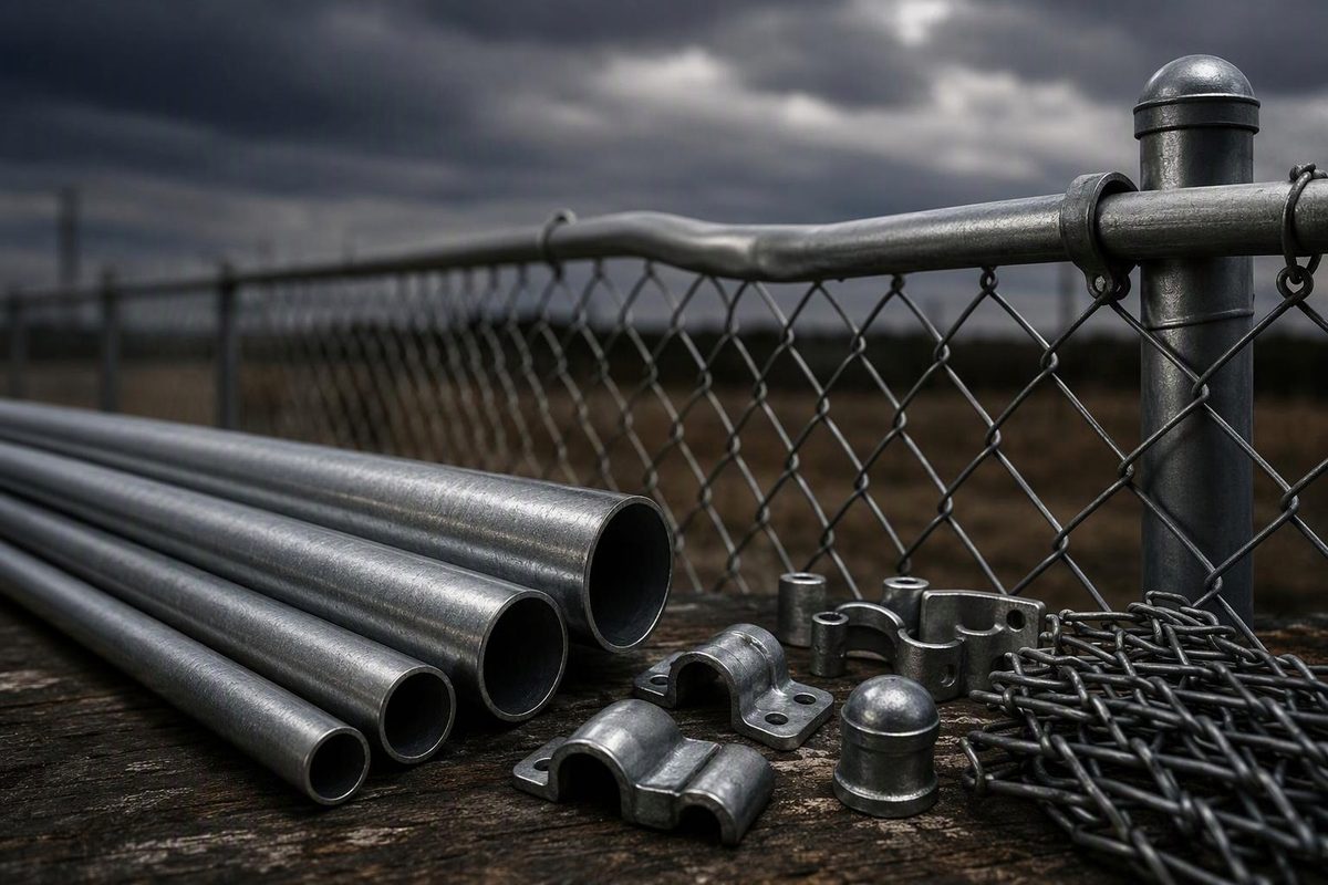
The top rail is the horizontal tube along the upper edge of a chain-link fence. For many residential systems, 1-3/8-inch outside-diameter (OD) galvanized tubing is the standard starting point, but heavy-industrial specifications may use 1.660-inch OD rail. Match replacement rail to the existing framework, fittings, wall specification, finish, and joint type rather than buying by fence height alone.
Top rail passes through loop caps on the line posts and terminates in rail-end fittings at end, corner, and gate posts. It supports the fabric’s upper edge and provides a continuous line for fence ties.
Enter the rail footage, uninterrupted runs, and line posts to estimate the main top-rail parts.
Top-Rail Material Estimator
Use fence footage that will actually receive rail. Treat each section interrupted by a gate or corner as a separate run.
- Rail sections
- —
- Loop caps
- —
- Rail-end assemblies
- —
Top Rail Is Framework, Not Trim
Chain-link fabric is stretched between terminal posts. The top rail connects the intermediate line posts, supports the fabric’s upper edge, and helps the fence remain aligned.
It is distinct from three other components:
- Brace rail: A shorter horizontal member near an end, corner, or gate post, often paired with a diagonal truss rod on taller or heavier fences.
- Bottom tension wire: Taut wire near the bottom of the fabric that helps resist lifting and curling.
- Top tension wire: Wire used in some rail-less systems instead of top rail.
The Chain Link Fence Manufacturers Institute (CLFMI) specification allows an upper tension wire where no top rail is installed. It also requires terminal-post bracing and trussing for a 5-foot fence without top rail. Replacing damaged rail with wire is therefore a system change, not a like-for-like repair (CLFMI chain-link specification).
Specify Top Rail With Four Measurements
Match the Outside Diameter
Measure across the outside of the existing tube, not across its opening. Check the rail-end cup and line-post loop as well because all three parts must fit together.
One residential materials list specifies 1-3/8-inch OD top rail in 10-foot-6-inch swaged lengths, paired with caps for 1-5/8-inch line posts and 1-3/8-inch rail (Merchants Metals planning guide). In contrast, CLFMI’s ASTM F1043 heavy-industrial framework specification lists round top, brace, bottom, and intermediate rail at 1.660 inches OD (CLFMI commercial and industrial specification).
That difference is why “chain-link top rail” is not a complete order description. Check the post sizes used elsewhere in the system, too.
Confirm Wall Thickness or Framework Grade
Two rails with the same OD can have different wall thicknesses, weights, and strengths. Retail descriptions may identify tubing by gauge, while commercial specifications may use an ASTM framework group, weight per foot, or wall thickness. Ask for the actual specification rather than assuming every 1-3/8-inch rail is equivalent.
Light residential rail may suit an ordinary short enclosure. A taller fence or a site exposed to repeated contact or impact may call for heavier framework. Privacy slats and screens require particular care because they increase wind load. CLFMI calls for wind-load analysis for fences with privacy products and for certain fences over 8 feet with mesh of 1 inch or smaller (CLFMI Product Manual).
Match the Finish and Coating System
Match galvanized rail to galvanized framework and polymer-coated rail to a coated system. For black, green, or brown fencing, confirm the color and coating system rather than relying on the color name alone. A replacement can be conspicuous even when its diameter is correct.
Identify the Joint Style
Swaged rail has one reduced end that slips into the full-size end of the next section. Plain-end rail requires a separate top-rail sleeve at each joint.
Do not order a sleeve until its listed fit matches the rail OD. ASTM F626 covers chain-link fittings including line caps, rail ends, sleeves, ties, and bands, but an ASTM reference does not eliminate the need to match dimensions (ASTM F626-14(2023) scope).
Write the order as a complete line item: OD × wall thickness or framework grade × length × swaged or plain end × galvanized or polymer finish.
Count the Parts for Each Uninterrupted Run
A conventional top-rail installation normally requires:
- Top rail for the fence length, excluding gate openings
- One loop cap for each line post
- One rail end at each terminal end of a run
- One rail-end or brace band and carriage bolt for each rail end
- Sleeves for plain-end rail, or compatible swaged joints
- Fence ties compatible with the rail and fabric finish
A corner post ends one run and starts another, so it generally needs one rail-end assembly from each direction. A gate opening also interrupts the run. Ordinary top rail should not span unsupported across the opening.
Estimate rail quantity from the system’s stated coverage rather than multiplying its nominal tube length. The Merchants Metals list calls for 10-foot-6-inch swaged rail but estimates quantity by dividing fence footage by 10, allowing for joint overlap and the final cut. The manufacturer’s layout should control the final count.
The number of sleeves cannot be established from total footage alone. It depends on whether the rail is plain-ended or swaged and how sections and cut pieces are distributed among the runs.
Install the Rail Before Final Fabric Tensioning
- Check the posts. Terminal and line posts should be plumb, aligned, at the correct elevations, and adequately set. Top rail will not correct leaning posts or weak footings.
- Install the terminal fittings. Fit the rail-end bands and rail ends to end, corner, and gate posts, then install the terminal-post caps.
- Fit loop caps to line posts. Orient the offset opening toward the outside or fabric side as directed by the system instructions.
- Start at a terminal post. Pass the rail through the loop caps. Join compatible swaged ends directly; use correctly sized sleeves for plain ends. CLFMI’s heavy-industrial specification requires sleeves at least 6 inches long, while a residential system may specify different fittings (CLFMI framework installation specification).
- Cut the last section square. Wear eye and hand protection, support the tube, and measure to the inside of the far rail end while allowing for joint engagement. Deburr the cut. For galvanized framework, protect damaged or bare areas using the rail manufacturer’s instructions; the CLFMI specification references ASTM A780 for repair of damaged galvanized coatings (CLFMI Product Manual).
- Seat and bolt the rail ends. The completed run should be continuous and snug without pulling terminal posts out of plumb.
- Hang, stretch, and tie the fabric. Install the rail before final fabric tensioning.
Tie spacing depends on the governing system. CLFMI’s commercial specification limits spacing along rail to 18 inches, while the Merchants Metals residential guide uses approximately 24 inches. Follow the plans or instructions for the framework and fabric being installed rather than combining requirements from different systems (CLFMI specification; Merchants Metals residential guide).
Replace a Bent Section Without Removing the Whole Run
A localized bend usually does not require replacement of the entire top-rail run:
- Untwist and remove the fabric ties around the damaged section.
- Support the fabric and locate straight tube beyond both ends of the bend.
- Wear appropriate eye and hand protection, then cut out the damaged rail with square cuts.
- Fit a replacement with matching OD, wall specification, finish, and joint type. Use its swaged end where possible and a correctly sized sleeve or coupling at the other joint.
- Loosen the terminal rail end if necessary to create enough movement for assembly.
- Reseat the run, tighten the terminal fitting, and install compatible ties.
Lowe’s published repair sequence likewise uses a swaged replacement at one end, a rail coupling at the other, and temporary loosening of the terminal rail end to make the connection (Lowe’s bent-rail repair guide).
If the replacement bends again, inspect the line posts, terminal bracing, and footing movement rather than treating the tube as the only possible problem.