
How to Build a Gate That Catches Reliably Every Time
Separate closing, latching and locking; match hardware to the gate’s swing, material and dimensions; then test partial, full-open and slow closure.
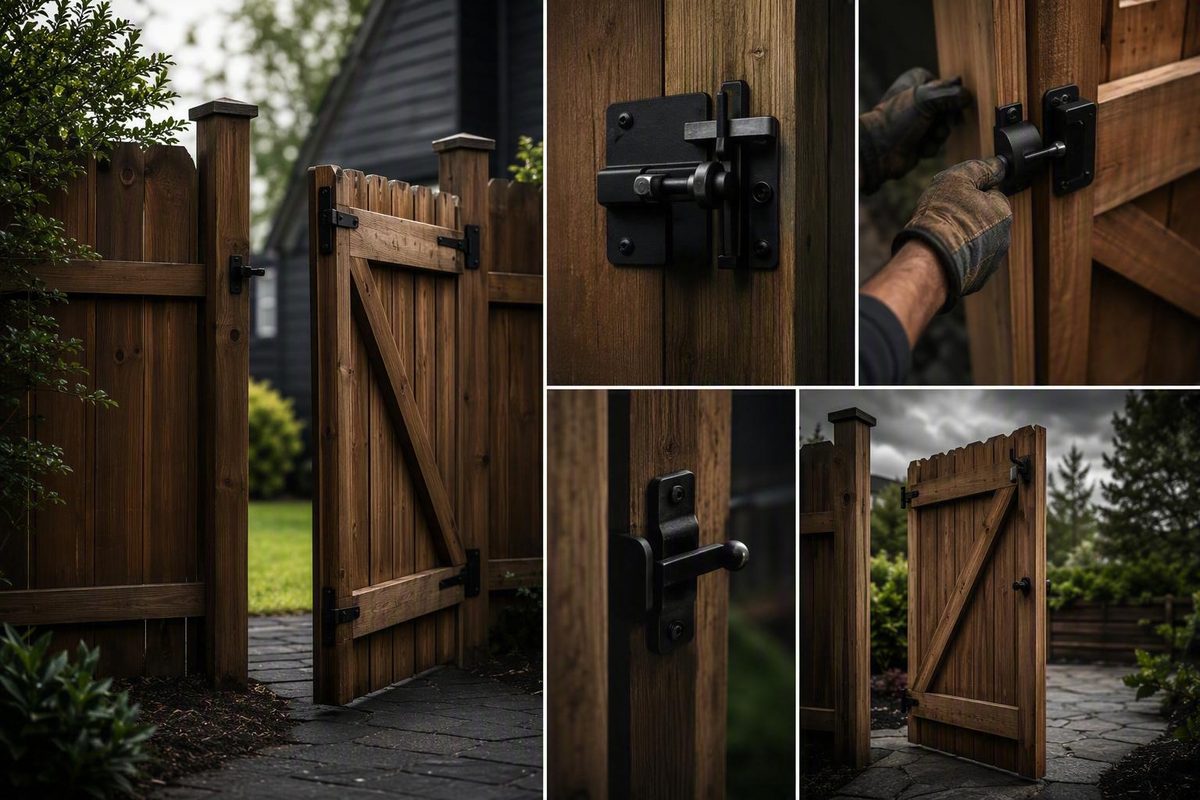
A reliable self-latching gate is a system, not simply a latch screwed to a post. The gate must travel freely, the hinges or closer must provide suitable movement, and the latch must meet its striker or keeper at the correct position with enough controlled force to engage.
Start by separating three jobs:
- Closing: What moves the released gate back to the closed position?
- Latching: What catches the gate automatically when it arrives?
- Locking: What prevents someone from operating the release?
That distinction prevents a common purchasing mistake: buying a “self-latching” product and expecting it to move an open gate. Choose a mechanism compatible with the gate’s material, dimensions, swing, access needs, and environment. Install it on sound structure, test it under several closing conditions, and correct sag or misalignment rather than relying on momentum.
Self-latching, self-closing, and self-locking are three different functions
A self-latching gate has a latch that engages automatically once the gate reaches the closed position. The user does not have to drop a bolt, rotate a lever, or place the latch arm into its keeper by hand.
A self-closing gate uses hinges, a closer, or another mechanism to return the released gate to the closed position. The closing device supplies movement; the latch does not.
A self-locking gate automatically locks after closing.
| What closes it? | What catches it? | What locks it? |
|---|---|---|
| Spring-loaded hinges, a dedicated closer, or another self-closing mechanism moves the gate toward the closed position. | A gravity, spring-loaded, butterfly, magnetic, or other automatic latch engages when the gate reaches its keeper. | A key cylinder, padlock, integrated lock, or other access-control mechanism prevents ordinary release. |
| Needed when the gate must return automatically after release. | Needed when the gate must catch without someone manually setting the latch. | Optional for many ordinary yard gates, but potentially necessary for security or controlled access. |
| Must suit the gate’s dimensions, weight, hinges, swing, and mounting arrangement. | Must suit the swing direction, gate gap, mounting surfaces, and available closing force. | Must preserve the intended release method and does not prove that the gate will latch reliably. |
A self-latching latch therefore does not move an open gate. Hands-free closing and latching generally require both an automatic latch and compatible self-closing hinges or a separate closer. Retailer guidance from 360 Yardware explains the same three-part distinction, although it is not a governing technical or legal standard.
“Spring-loaded” can describe two components with different jobs:
- A spring-loaded hinge moves the gate.
- A spring-loaded latch resets or advances the latch mechanism so it can catch.
Installing a spring-loaded latch does not turn ordinary hinges into self-closing hinges. Installing self-closing hinges likewise does not guarantee that a poorly aligned latch will engage. Closing force, final alignment, and the latch’s operating path must work together.
For an ordinary yard gate, closing and latching may be all you need. A gate protecting a restricted area may also require access control. Decide that deliberately rather than treating “automatic,” “safety,” “security,” “lockable,” and “self-locking” as interchangeable labels.
Choose the latching mechanism before choosing a product
Product listings can make dissimilar devices sound equivalent. A better approach is to decide how the latch should operate and then look for a product that documents the required fit.
The mechanisms considered here are gravity latches, spring-loaded or butterfly latches, and magnetic latches. The available evidence does not establish any one category as universally safest, longest-lasting, or most reliable. Performance depends on the gate, installation, adjustment, closing hardware, and operating environment.
| Comparison point | Gravity latch | Spring-loaded or butterfly latch | Magnetic latch |
|---|---|---|---|
| Mechanism | A moving arm or catch rises or shifts as the gate closes, then falls into the holding position by gravity. | A spring returns wings, a bolt, or another catch into the engaged position as the gate arrives. | A magnet draws a latch bolt between mating housings as the gate shuts. |
| Typical gate configuration | Common on wood and general-purpose pedestrian gates; mounting varies by product. | Butterfly designs are common on round-frame chain-link pedestrian gates; other spring latches suit different gate constructions. | Often marketed for safety-sensitive pedestrian gates, but compatibility is model-specific. |
| One-way or two-way swing | Varies. The documented outswing example is one-way only. | Varies. The documented butterfly example supports inward or outward swing. | Depends on the complete gate and hinge layout; do not infer swing direction from “magnetic.” |
| Separate closer needed? | Yes, if the gate must return automatically. | Yes, if automatic return is required. The latch spring moves the latch parts, not the gate. | Yes, unless the latch is supplied as part of a system with self-closing hinges or a closer. |
| Lock options | May be non-locking or padlockable. | The documented butterfly example is non-locking; other designs vary. | Key-lockable models are sold, but magnetic action does not necessarily mean automatic locking. |
| Key compatibility checks | Swing direction, orientation, keeper alignment, gate gap, release arrangement, and padlock clearance. | Frame and post dimensions, wing alignment, closing force, swing direction, and clamp fit. | Gate gap, housing alignment, brackets, release position, gate material, hinge arrangement, and adjustment range. |
| Evidence limitations | Retail guidance indicates that realignment may sometimes be needed, but this is not comparative proof for the entire category. | One product documents useful dimensions and operating requirements that cannot be generalized to every butterfly latch. | Commercial system descriptions explain operation but do not establish category-wide superiority or local compliance. |
Gravity latches
A gravity latch can engage automatically when the gate closes. Engagement still depends on the striker arriving at the correct height and depth, so gate sag or post movement can create a need for realignment.
As one bounded example, HardwareSource lists a zinc-finished steel gravity latch for a single-acting outswing gate. In that arrangement, the latch mounts inside the gate and the striker mounts on the post or wall. The product includes matching wood screws, has a padlock eye, and provides a release-lever hole for an optional opposite-side cord or wire. The padlock is not included, and the product is not documented for a two-way gate. These details apply to that specific outswing gravity latch, not to gravity latches as a class.
A gravity latch may make sense when the gate has a predictable one-way swing, the hardware can be mounted to sound structure, and its alignment can be inspected when operation changes. Do not assume “gravity latch” means that gravity closes the gate; automatic movement requires appropriate hinge geometry or separate closing hardware.
Spring-loaded and butterfly latches
A spring-loaded latch uses spring force to return its bolt, arm, or wings to the engaged position. As the gate closes, the post lifts the wings, which then drop around it.
Signet Fence’s documented galvanized-steel butterfly latch is intended for residential chain-link pedestrian gates and is described as bidirectional for inward or outward swing. It is non-locking and requires enough closing force to lift and engage the wings. Listed options fit gate-frame outside diameters of 1-3/8 or 1-5/8 inches and terminal-post outside diameters of 2 or 2-1/2 inches; a 3/8-inch U-bolt is included. Those are product-specific butterfly-latch dimensions, not standard sizes for all chain-link hardware.
This type can be useful where a pedestrian gate may swing either way and where the round gate frame and terminal post match the latch. Bidirectional operation does not cure poor alignment or weak closure. If the gate reaches the post without enough controlled force to lift the wings, it may stop without catching.
Magnetic latches
The magnet performs the latching action; it does not necessarily move the gate from an open position.
Life Saver’s marketed pool-gate arrangement illustrates the complete-system distinction. It pairs adjustable TruClose self-closing hinges with a key-lockable MagnaLatch. Life Saver says a permanent magnet draws the latch bolt between the housings as the gate shuts, while an internal torsion spring in the hinges supplies closing force. Life Saver also reports more than 400,000 latch cycles, but the supplied page does not identify the laboratory, protocol, report, or exact tested model. That figure should therefore be treated as an attributed commercial claim, not independent comparative evidence. The Life Saver system description also does not by itself establish approval in a particular jurisdiction.
Mechanism is only the first filter. Once you know whether the gate calls for a gravity, spring-loaded, butterfly, or magnetic arrangement, compare exact dimensions, mounting requirements, adjustment limits, lock options, and installation documentation.
Match the hardware to the gate, not just the product label
A label such as “automatic gate latch” tells you what the seller intends the mechanism to do. It does not establish that the latch fits your gate or that the gate supplies the movement needed to operate it.
Use this decision tree before shopping:
-
Identify the gate’s use. - Ordinary garden or yard access - Animal enclosure - Security-sensitive entrance - Pool or other safety-sensitive barrier - Accessibility-sensitive route
-
Identify the material and structural mounting surfaces. - Wood frame - Round chain-link frame - Fabricated steel or aluminum - Vinyl with internal reinforcement or manufacturer-defined mounting points
-
Identify the swing. - Inward only - Outward only - Either direction - Left- or right-handed layout - Relative to any restricted area
-
Decide whether automatic closing is required. - If no, select a self-latching mechanism that catches when someone pushes the gate closed. - If yes, select compatible self-closing hinges or a closer as well as the latch.
-
Decide how people will operate it. - From one side only - From both sides with purpose-built handles or releases - Through a manufacturer-approved opposite-side linkage - With keyed, padlocked, alarm-equipped, self-locking, or non-locking hardware
-
Verify dimensions and exposure. - Frame and post size - Gate-to-post gap - Mounting clearance - Gate dimensions and weight - Environmental exposure - Adjustment range
Wood gates
Attach latch hardware to the structural gate frame rather than relying on a decorative picket. In one documented sponsored retrofit, hardware previously attached to a picket came away after the picket split during a storm; the replacement was moved to the gate support. Treat that as an installation example rather than independent product testing.
Check that the specified screws suit the gate construction, available wood thickness, hardware holes, and outdoor exposure. They should enter sound structural material without protruding into a hand path. If the supplied fasteners are unsuitable, obtain replacement specifications from the latch or gate manufacturer rather than substituting by appearance alone.
Swing also matters. The documented HardwareSource gravity latch is expressly limited to a one-direction outswing gate. Do not select it for a gate intended to swing both ways merely because its striker looks accessible from either direction.
Chain-link gates
For chain-link hardware, measure the outside diameter of:
- The gate frame where the latch will clamp
- The terminal or latch post that the gate meets
The butterfly-latch example’s separate frame and post options show why both measurements matter. Your gate may use different tubing, so do not infer diameter from fence height or residential appearance.
Inspect the gate’s final travel as well. The wings must align with the terminal post, and the gate must arrive with enough force to lift them. If automatic closure is required, verify that the selected hinges or closer can move the complete gate through that resistance.
Metal gates
“Metal gate compatible” can refer to very different constructions, including hollow aluminum sections, steel tubing, welded frames, or decorative panels. Verify with the gate and latch documentation:
- Which locations are approved for mounting
- Whether drilling or other modification is permitted
- Which bracket and fastener system is required
- Whether reinforcement is necessary
- Whether the required gate gap can be maintained
- Whether adjustment remains accessible after installation
Do not assume that thin decorative infill is an adequate mounting surface when the gate has a structural stile. If the instructions call for structural modification or fabrication beyond your experience, use a qualified professional.
Vinyl gates
Determine where the gate has internal reinforcement and whether the gate manufacturer permits latch installation there. Use the specified brackets and fasteners, and verify that the installed gate gap falls within the latch’s documented range.
Retail category labels are not engineering confirmation. Listings may group hardware marketed for wood, metal, and vinyl gates together, but the category does not prove dimensional fit, structural suitability, corrosion resistance, or reliable operation.
One-sided versus two-sided access
Some latches have purpose-built handles or connected mechanisms on both sides. Others operate directly from one side and use a separate approved linkage for the other.
The documented gravity latch includes a hole for a release cord or wire, but that does not make every improvised pull arrangement appropriate. An opposite-side pull can affect:
- Child access
- Tamper resistance
- Security
- Reach and usability
- Snagging and weather exposure
For a safety-sensitive or security-sensitive gate, use a purpose-built two-sided mechanism or the manufacturer’s approved arrangement. Do not add an improvised string or wire without determining whether it defeats the gate’s intended function.
Define “lockable” accurately:
- Non-locking: Catches but provides no lock.
- Padlockable: Accepts a separate padlock.
- Keyed: Incorporates or works with a key cylinder.
- Alarm-equipped: Signals operation but does not necessarily lock.
- Self-locking: Locks automatically after closure.
None of these labels proves reliable latching, dimensional compatibility, or suitability for a regulated barrier.
Measure the gate and document the missing specifications
Measure the installed gate, not an old receipt or the opening as it existed before the gate was hung. Record the gate’s condition as well as its dimensions. Otherwise, measurements taken from a sagging gate can lead you to fit new hardware around an unresolved defect.
Printable measurement worksheet
| Item | Measurement or answer |
|---|---|
| Gate use | ______ |
| Gate material | ______ |
| Gate width | ______ |
| Gate height | ______ |
| Gate weight, if known | ______ |
| Gate-frame dimensions or tube outside diameter | ______ |
| Latch-post dimensions or outside diameter | ______ |
| Gate-to-post gap at latch height | ______ |
| Gap at top and bottom for comparison | ______ |
| Flat mounting area on gate | ______ |
| Flat mounting area on post or frame | ______ |
| Clearance for latch movement | ______ |
| Clearance for hands, padlock, or key | ______ |
| Structural attachment points | ______ |
| Current hinge type and condition | ______ |
| Swing: inward, outward, or both | ______ |
| Swing relative to restricted area | ______ |
| Handing, viewed from approach side | Left / Right |
| Automatic closing required? | Yes / No |
| Access needed from | One side / Both sides |
| Desired release location | ______ |
| Lock type | None / Padlock / Key / Other |
| Alarm needed? | Yes / No / Undecided |
| Exposure | Inland / Poolside / Coastal / Road salt / Other |
| Existing sag, drag, or post movement | ______ |
| Product or code documentation still needed | ______ |
Measure the gate-to-post gap where the latch will sit, then compare the top and bottom gaps. Determine whether the gate is genuinely one-way or two-way and record whether it swings inward, outward, or relative to a restricted area.
Inventory the package contents, but do not assume that included hardware suits every substrate or exposure. Knowing what is supplied prevents duplicate purchases while also identifying specifications that still need confirmation.
Pre-purchase evidence checklist
Ask the seller or manufacturer for written answers covering:
- Minimum and maximum gate dimensions
- Gate-weight limit for hinges or closer
- Compatible gate and post materials
- Required gate gap
- Adjustment range in each direction
- Supported swing direction and handing
- Required brackets or reinforcement
- Required closing performance, if specified
- Closing-speed or tension-adjustment method
- Documented corrosion test or exposure rating
- Cycle-test method, tested model, and result
- Named certifications, listings, or approvals
- Installation and adjustment instructions
- Maintenance instructions
- Replacement-part availability
- Full warranty terms, exclusions, and claims procedure
Material and coating labels are only starting points. “Zinc-finished,” “galvanized,” “powder-coated,” or “stainless” does not by itself establish suitability beside a pool, at the coast, near road salt, or where different materials meet. Ask for the exact grade, coating specification, test result, and environmental limitations applicable to the product.
Treat customer reviews as anecdotes. They may reveal a fit problem worth investigating, but a few favorable comments cannot establish service life, corrosion resistance, safety, or value. Apply the same caution to uncited promotional phrases such as “heavy duty,” “pool safe,” or “most reliable.”
Keep a small project file containing the worksheet, product model, instructions, seller answers, receipts, and photographs of the gate before installation. That record will make later adjustment and replacement easier.
Install the latch on sound structure and align the moving parts
The following are general installation principles, not a substitute for the exact product instructions. The manufacturer’s specified dimensions, fasteners, clearances, tension limits, and safety warnings control for the installed hardware.
1. Correct the gate before adding the latch
Open and close the gate by hand. Inspect:
- Hinges for looseness, wear, or bending
- Hinge fasteners and mounting surfaces
- Gate frame for racking or sag
- Post for movement, rot, cracking, or loss of plumb
- Bottom edge for ground contact
- Swing path for vegetation, stones, edging, hoses, or other obstructions
- Existing hardware for corrosion or damage
A new latch should not be used to pull a sagging gate into position. If the gate drags, twists, or moves at its joints, correct that condition before locating the latch.
2. Identify the structural mounting points
On a wood gate, locate the stile, rail, or braced frame behind the face boards. On metal or vinyl, identify manufacturer-approved or reinforced locations. On chain link, confirm that the clamp matches the measured tube diameter without unapproved shimming.
Check both sides before drilling.
3. Understand the two-component relationship
- One component on the moving gate
- A striker, keeper, catch, or latch housing on the post or fixed frame
Which component goes where varies. Some gravity latches place the latch body on the post; some adjustable systems use a bar on the gate and a striker on the post; magnetic systems use paired housings. Follow the product diagram rather than relying on a familiar-looking arrangement.
4. Establish the operating position
Close the gate naturally against its intended stop. Do not lift it by hand to make the parts align. Position the first component where it can attach to structure and where the release remains usable.
A workable wood-gate sequence is:
- Position and mark the first component.
- Predrill if the instructions require it.
- Fasten the component while preserving any movement built into the design.
- Move the latch through its operating path.
- Use that path to locate the mating striker or keeper.
- Mark, predrill, and fasten the mating component.
- Cycle the gate before making final permitted adjustments.
A sponsored DIY retrofit used a pilot bit slightly narrower than the screw so the threads could engage the wood. It also mounted the gate-side component first and used its operating path to locate the striker. These are useful examples, but the fastener and hardware instructions should control because screw geometry and wood conditions vary. See the documented self-adjusting latch installation for the bounded project example.
5. Do not eliminate designed movement
Some latch arms are designed to float through a small vertical range, while some striker plates use elongated slots for adjustment. Overtightening a joint intended to pivot or float can prevent engagement.
“Self-adjusting” does not mean unlimited correction. Limited movement may accommodate minor variation, but larger shifts require manual realignment. Significant sag, post movement, or mounting damage must be corrected at the source.
6. Align chain-link butterfly hardware around the post
For the documented butterfly design, the latch clamps to a correctly sized gate frame. Position the wings so the terminal post enters centrally and lifts them as the gate arrives. Tighten the clamp evenly, verify that the latch does not rotate during operation, and confirm that the wings drop fully after passing the post.
If the gate stalls against the wings, first verify tube sizes, vertical alignment, centering, free wing movement, and the absence of binding. Do not immediately increase closing force to conceal a fit problem.
7. Test before declaring the work complete
Visual alignment is not enough. Operate the release from every intended side, move the gate through its full swing, and test automatic engagement under partial, full-open, and slow-closing conditions. Only after the gate operates consistently should you make final permitted adjustments and recheck the fasteners.
Test from partial, full, and slow-closing positions
Testing has two distinct parts:
- Gate-movement test: Does the released gate travel to the closed position without help?
- Latch-engagement test: Once the gate arrives, does the latch catch and hold?
A gate can pass one test and fail the other. Strong closing hardware may move the gate while a high striker misses the keeper. Conversely, a correctly aligned latch may catch whenever someone pushes the gate closed even though the gate has no automatic closer.
Partial-opening test
If the gate is intended to self-close, open it partway and release it without pushing. Stand clear of the swing path. Confirm that it:
- Begins moving without guidance
- Continues through the remaining path
- Does not drag or bind
- Reaches the closed position
- Engages the latch
This test can expose insufficient final closing force or resistance near the latch that may not be obvious when the gate starts with more momentum.
Full-open test
Open the gate to its normal full-open position and release it. Observe the entire path for:
- Ground contact
- Hinge binding
- Weak or uneven closer action
- Obstructions
- Contact with stops, walls, vegetation, or fencing
- Excessive speed or rebound
Do not hold or steer the gate. The purpose is to observe how the complete system behaves when released normally.
Slow-closing test
Move or release the gate so it approaches the latch slowly, without a slam. The latch should engage without depending on extra momentum. If it works only when the gate is thrown shut, investigate alignment, resistance, gate gap, and closing force.
Sufficient closing force is necessary, but slamming is not a substitute for correct fit.
Secure-engagement test
Listen or look for positive engagement. Apply light pulling pressure without touching the release. The gate should remain caught. Watch the mechanism while doing this: a latch resting on the edge of its keeper has not passed merely because the gate appears closed.
Repeatability test
Repeat the partial-opening, full-open, slow-closing, and light-pull checks several times. Pool Guard USA recommends three to five repetitions and a complete retest after adjustment; that is commercial provider guidance rather than a universal code procedure. Its pool-gate testing guide also distinguishes slow closure from a momentum-assisted slam.
| Test | Pass | Fail | Notes |
|---|---|---|---|
| Travels from partial opening without help | ☐ | ☐ | |
| Travels from full opening without help | ☐ | ☐ | |
| Engages during slow closure | ☐ | ☐ | |
| Holds under light pull without release | ☐ | ☐ | |
| Repeats consistently | ☐ | ☐ | |
| Release works from every intended side | ☐ | ☐ | |
| No dragging, binding, or obstruction | ☐ | ☐ |
After any repair or adjustment, repeat every test. Increasing hinge tension might solve stalling but create excessive speed or rebound. Moving a keeper may improve engagement while reducing release clearance. Test the complete system, not only the component you changed.
Troubleshoot a gate that closes but misses the latch
- The gate is not arriving in the correct position.
- It is not arriving with suitable controlled force.
- The latch cannot move freely.
- The structure is changing under load or environmental conditions.
| Symptom | Likely checks | Corrective direction |
|---|---|---|
| Gate misses the keeper | Vertical and horizontal alignment; sag; post movement; loose screws or clamps; bent striker; worn latch; changing gap | Restore the gate and post, secure sound connections, then adjust within the documented range or replace damaged parts |
| Gate bounces back open | Full latch entry; closing speed; final approach; stop position; latch resistance; obstruction inside keeper | Align for full entry, remove binding, and adjust closing action only as instructed |
| Gate drags | Ground clearance; hinges; racked frame; swollen or warped material; leaning post | Correct the structural or clearance problem before realigning the latch |
| Gate stalls before latching | Hinge or closer tension; weight compatibility; latch resistance; wind; binding; obstruction | Remove resistance, verify hardware capacity, and make only documented adjustments |
| Gate must be slammed | Alignment; closing force; gate gap; corrosion; incorrect orientation | Correct fit and free movement rather than accepting slamming as normal |
| Closure is weak | Tension setting; damaged closing hardware; gate weight; hinge friction; added load | Verify capacity and condition, then adjust or replace with compatible closing hardware |
| Failure is intermittent or seasonal | Post movement; wood movement; clearance changes; loose clamps; corrosion; vegetation | Correct the source and inspect after noticeable environmental or operating changes |
If the striker misses the keeper
Close the gate slowly while watching the parts meet. Look from above and from the side. Determine whether the error is:
- Vertical: The striker is too high or low.
- Horizontal: It is too far in, out, forward, or back.
- Angular: The gate or post is twisted.
- Dynamic: Alignment changes during the final part of travel.
Check the hinges and frame before moving the latch. If the gate drops when unlatched, hinge looseness or frame sag may be the real problem. If the post moves when pushed, latch adjustment alone will not hold.
Tighten hardware only into sound material. A screw spinning in damaged wood or a clamp rotating on mismatched tubing is not a successful adjustment.
If the gate bounces open
Confirm that the latch enters fully.
Check the gate stop, hinge or closer setting, latch movement, and gate gap. Adjust closing action only within the manufacturer’s instructions, then repeat the slow-closing and secure-engagement tests.
If the gate stalls or closes weakly
Determine whether the resistance begins before or at latch contact. If the gate slows earlier in its swing, inspect the hinges, closer settings, ground clearance, warping, and swing-path obstructions. If it stops only when the latch parts meet, inspect alignment and the force required for engagement.
Recheck compatibility whenever the gate’s construction or weight changes.
If it works only when slammed
That does not make the setup dependable.
Clean, maintain, adjust, or replace components only as the applicable instructions allow. Recheck the gate gap, orientation, sag, and closing force. A slow-close failure is evidence that the gate and latch are not working together consistently.
Product-specific adjustment example
For one pictured MagnaLatch arrangement, Protect-A-Child directs users to compare front and side alignment marks, use a set screw for horizontal movement, reposition the latch vertically after removing a side screw, and check operation afterward. The provider reports up to 1 inch of horizontal adjustment in either direction for that configuration. These are specific MagnaLatch adjustment instructions, not a universal range or procedure.
Never force a latch beyond its documented slots or travel. If adjustment runs out, look for a structural cause. Minor movement may remain within the latch’s adjustment range; substantial sag, post movement, damaged hinges, severe corrosion, cracked mounting material, or bent hardware requires repair or replacement.
Inspect the gate after storms, impacts, soil movement, landscaping changes near the posts, or any noticeable change in operation. Check alignment, fasteners, corrosion, hinge or closer action, and swing-path clearance. Follow the product’s maintenance instructions rather than imposing one schedule on every gate and environment.
Treat pool gates as a separate safety and code project
A pool gate should not be specified as an ordinary garden gate with a “pool” latch added at the end. Commercial pool-safety guidance treats automatic closing and automatic latching as separate parts of the complete gate system, but the supplied commercial sources do not establish the controlling law for every location.
Before buying or positioning hardware:
- Identify the government department or other authority responsible for the property.
- Ask which code or regulation currently applies.
- Obtain any applicable local amendments and inspection instructions.
- Confirm whether the exact gate, fence, and hardware arrangement needs a named listing, certification, or approval.
- Verify applicable rules for swing, release position, openings, access, and operation from that controlling source.
Do not treat dimensions, latch heights, swing rules, or inspection procedures published by a retailer as universal law. One fence supplier, for example, summarizes pool-gate rules for particular Texas-area jurisdictions, but its commercial pool-gate hardware guide is not the adopted code or an official interpretation.
A product is not proven suitable for a regulated pool barrier merely because it is:
- Self-latching
- Key-lockable
- Alarm-equipped
- Magnetic
- Marketed as a safety latch
- Advertised as “pool safe”
Ask for the exact model, official installation instructions, named certification or listing, and any limits involving gate material, dimensions, gap, hinges, or mounting. Confirm that the documentation applies to the complete installed arrangement rather than a similar product family.
Pool-gate verification should include automatic travel and engagement from partial, full-open, and slow-closing positions, followed by a check that the latch holds without operating the release. If the gate fails, restrict access until the cause has been corrected and the entire sequence has been retested; this is safety guidance from a commercial pool-barrier provider, not a substitute for local inspection requirements. Pool Guard USA gives the same restrict-access and retest direction.
Stop DIY work and contact the relevant building department, pool inspector, qualified fence professional, or hardware provider when:
- Local requirements are unclear
- The gate has unusual swing or geometry
- Accessibility requirements affect opening force or release placement
- The post, frame, or hinge mounting is damaged
- The product lacks adequate installation or certification documentation
- Adjustment cannot produce consistent slow-close engagement
- Repair requires structural modification or work outside your experience
Frequently asked questions
Does a self-latching gate close by itself?
Not necessarily. “Self-latching” means the latch engages automatically after the gate reaches the closed position. Self-closing hinges, a separate closer, or another compatible mechanism must move the gate if it is expected to return from open without being pushed.
Can a self-latching gate also be locked?
Yes, if the selected hardware has an appropriate locking function. Options include padlockable latches, keyed locks, and integrated systems that retain automatic latching.
A lock does not prove that the latch engages reliably. A padlockable latch is also not the same as a self-locking latch: the former accepts a manually fitted lock, while the latter locks automatically after closure.
Can a self-latching latch open from both sides?
Some can. Purpose-built two-sided latches may have handles or connected releases on both sides. Other designs operate directly from one side and use a manufacturer-provided linkage for the other.
The documented one-way gravity latch, for example, has a release-lever hole for an optional cord or wire. Before using such an arrangement, consider child access, tampering, security, snagging, and usability. Do not improvise an opposite-side pull on a safety-sensitive gate without appropriate product and regulatory guidance.
Why does my gate close but fail to catch the latch?
Common causes include vertical or horizontal misalignment, gate sag, a shifting post, loose fasteners, bent or worn parts, corrosion, inadequate final closing force, and obstructions.
Watch the latch and keeper meet during a deliberately slow closure. Correct the structural or alignment problem instead of relying on a slam. If the latch is adjustable, stay within its documented range and repeat the complete test after adjustment.
Is every self-latching gate suitable for a pool fence?
No. Self-latching describes only one function. Commercial pool-safety guidance calls for a complete gate that closes and latches automatically, but the exact legal requirements depend on the rules adopted for the property.
Key locking, alarms, magnetic action, and “pool safe” marketing do not establish compliance by themselves. Verify the exact model, official instructions, named certifications or approvals, complete gate configuration, and current local requirements. If the installed gate does not close and latch consistently, restrict access until it has been corrected and fully retested, consistent with the provider guidance cited above.
Conclusion
A reliable self-latching gate begins with three independent decisions: what closes it, what catches it, and what—if anything—locks it. Measure the gate and post, confirm the swing and structural mounting points, and select hardware with documented compatibility.
After installation, test the gate from partial, full-open, and slow-closing positions. Correct sag, weak closure, binding, and misalignment instead of relying on a slam. For a pool barrier or any safety-sensitive entrance, verify the controlling local requirements and exact product documentation before installation.